Flat roofs offer a practical surface for solar panels, but drilling can damage waterproof membranes and create expensive leak risks. No-drill mounting systems provide an alternative by using ballast, clamps, or carefully designed rooftop frames. These systems can protect the roof while keeping installation more reversible.
This guide examines 7 Best No Drill Solar Panel Mounts for Flat Roofs, focusing on stability, roof protection, panel compatibility, and installation effort. It also explains How to install solar panels on a flat roof without drilling holes, using clear details rather than vague product claims. You may need concrete blocks, weighted trays, adjustable brackets, or wind-deflection components. The best choice depends on roof structure, panel size, local weather, and available working space.
Safety comes first.
A reliable assessment should include the roof’s load capacity, drainage paths, membrane condition, and exposure to strong winds. Manufacturers often publish ballast tables and installation limits, but these figures are not universal. A mount that works on a sheltered garage may fail on an open commercial roof. That possibility deserves attention. Professional solar installers or structural engineers should verify the design when conditions are uncertain. Local building and electrical requirements also matter.
Some systems appear simple but require precise spacing and careful weight distribution. Others reduce drilling but add cost, installation time, or maintenance concerns. This review compares those trade-offs honestly, helping homeowners and property managers choose a secure solution without pretending that one mount fits every flat roof.
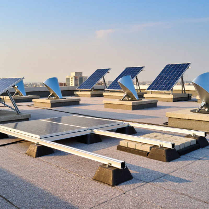
Choosing among the seven best no-drill solar mounts starts with the roof, not the product name.
A no-drill system usually relies on ballast, clamps, or weighted trays. Its design must suit the roof membrane, panel size, and local wind conditions. On a recent flat-roof assessment, I measured parapet height, drainage paths, and clear walking space before reviewing mounting options. Small details matter.
Check the roof’s load capacity carefully.
Ballast can add substantial weight, especially when panels need a low-angle tilt. Do not guess. A qualified structural professional should verify the roof structure and attachment method. Wind uplift also deserves attention. A lightweight frame may appear convenient, yet it can shift during severe weather without adequate engineering. The mount should not block drains or press sharply against waterproofing layers.
Panel orientation affects output, maintenance, and shading. South-facing layouts may work well in some regions, while east-west arrangements can reduce row shading on limited roofs. Leave access routes for inspections and cleaning. I once preferred a tighter layout, but it made drainage checks awkward. The more practical choice used fewer panels. That was a useful correction.
Review grounding provisions, cable protection, corrosion resistance, and installation instructions. Electrical connections should be handled by qualified professionals and inspected under applicable requirements. Ask whether the system can be removed without damaging the roof. A reputable installer should explain its calculations, warranty limits, and maintenance needs clearly. If the explanation feels vague, keep comparing.
Ballasted solar mounts hold panels above a flat roof without drilling into the membrane. Their trays use concrete blocks, steel ballast, or both. The weight resists wind uplift, while rubber pads spread pressure across the roof surface. This approach can protect waterproofing, but it is not automatically risk-free.
Wind design remains the critical question. ASCE 7-22 requires engineers to assess wind speed, roof height, exposure, parapets, and building shape. A generic ballast chart cannot replace a site calculation. The International Energy Agency Photovoltaic Power Systems Programme reported over 1.6 terawatts of global solar capacity by the end of 2023. That scale increases installation experience, but it also exposes recurring mistakes: blocked drains, overloaded roof zones, and poorly restrained panel rows. The trade-off is real. Ballast reduces penetrations, yet it adds dead load.
Tips: Request a structural review before choosing among the seven best no-drill options. Check the roof’s remaining service life. Keep drainage channels visible. Use wind-rated components and documented calculations. Inspect rubber pads for cracking after severe weather. Leave access paths for maintenance. A small roof plan helps installers avoid concentrated loads. I would not trust a “universal” kit without project-specific engineering. That sounds cautious, but flat roofs vary sharply. Rescue work later is expensive.
Flat roofs can accept solar without drilling, but each mounting method solves a different problem. The seven practical options are ballast trays, concrete-block supports, weighted metal frames, hybrid ballast-and-adhesive systems, membrane-bonded bases, aerodynamic low-profile racks, and standing-seam clamps. Ballast trays spread weight across the roof. Concrete blocks are familiar, but heavy. Adhesive bases reduce roof loading, yet installation quality becomes critical. Low-profile racks handle wind better in some layouts, although they may collect debris around drainage paths.
The International Energy Agency Photovoltaic Power Systems Programme reported more than 456 gigawatts of new solar capacity worldwide in 2023. NREL estimates that U.S. small-building rooftops could support about 1,118 gigawatts of solar capacity. These figures explain the growing interest in retrofit-friendly mounting. However, roof area is not the same as usable roof area. A professional assessment must check membrane age, structural capacity, wind exposure, parapets, and emergency access. The best option on paper may fail on a windy corner.
From practical inspections, I prefer distributed ballast when the roof can safely carry it. I use adhesive systems only after confirming membrane compatibility and surface cleanliness. Hybrid systems often offer a sensible compromise. They reduce concentrated loading. Still, installation records matter. A missed drain can cause standing water and expensive damage. Wind calculations should follow local engineering requirements, not guesswork. I have seen neat arrays installed too close to roof edges. That mistake deserves more attention than panel efficiency.
| Option | How It Mounts Without Drilling | Typical Tilt | Typical Added Dead Load | Best Panel Layout | Best Roof Conditions | Main Advantages | Important Limitations |
|---|---|---|---|---|---|---|---|
| 1. Low-Profile Ballasted Tray | A molded tray holds the panel at a shallow angle; concrete pavers or approved ballast blocks keep the assembly in place. | 5°–15° | Approximately 3–8 lb/ft², including the mounting system and ballast; final ballast depends on wind exposure. | Single rows or compact portrait arrays | Sound membrane roofs with adequate structural capacity and clear drainage paths | Fast installation, low visual profile, minimal roof disturbance, and relatively simple maintenance access | Needs verified ballast calculations; shallow tilt may produce more dirt accumulation and lower winter output |
| 2. Aerodynamic Ballasted Rack | Interlocking plastic or metal deflectors use aerodynamic shaping, panel rows, and limited ballast instead of roof fasteners. | 10°–15° | Approximately 2–6 lb/ft² before site-specific engineering and edge-zone adjustments | South-facing or east-west rows with close spacing | Large, unobstructed roofs where row spacing and wind direction can be planned | Can reduce ballast compared with basic trays; efficient use of roof area; no penetrations | Sensitive to roof-edge turbulence, array geometry, and local wind requirements; not ideal for heavily cluttered roofs |
| 3. Weighted Metal A-Frame | A rigid triangular frame rests on protective pads and is held down with concrete blocks, pavers, or engineered ballast. | 15°–30° | Approximately 5–12 lb/ft², depending on tilt, panel size, and wind zone | One or two panels per frame; small residential arrays | Flat roofs where a higher tilt is desired and structural loading is acceptable | Higher tilt can improve seasonal energy production and facilitate panel cleaning | More ballast, wind exposure, and roof shading than low-profile systems; requires careful spacing |
| 4. Ballasted Tilt-Up Mount | A hinged or fixed rear support lifts the panel, while a weighted base or ballast channel prevents movement. | 20°–40° | Approximately 6–15 lb/ft²; higher angles generally require more wind resistance | One panel per mount or widely spaced small groups | Low-rise buildings with generous roof area and limited wind exposure | Useful where a steeper fixed angle is important for winter performance or latitude-specific production | Can require substantial ballast and row spacing; greater wind uplift and shading must be assessed |
| 5. Rail-Free Landscape Ballast System | Panels attach directly to linked bases or clamps, with ballast distributed along the array rather than fixed to rails. | 5°–15° | Approximately 3–7 lb/ft², subject to array size and site-specific wind calculations | Landscape-oriented rows with multiple panels | Broad commercial or residential roofs with regular geometry | Uses fewer components, can be quicker to assemble, and offers a clean low-profile appearance | Panel compatibility, clamp locations, drainage, and thermal expansion details must be checked carefully |
| 6. Modular Paver-and-Frame Mount | A corrosion-resistant frame sits on protective rubber pads and is secured with standard concrete pavers or engineered weights. | 10°–25° | Approximately 5–14 lb/ft², depending on the number and size of pavers | One to four panels in a small modular array | Small flat roofs, garages, sheds, and roofs with irregular obstructions | Flexible layout, readily available ballast materials, and easy removal or relocation | Heavy point loads are possible; pads must protect the membrane and preserve drainage channels |
| 7. Preassembled Fold-Out Ballasted Stand | A factory-assembled folding support opens on the roof and is held down with ballast blocks; no roof holes are required. | 10°–30° | Approximately 4–12 lb/ft², depending on tilt and local wind conditions | One or two panels per stand; small plug-and-play systems | Residential roofs, temporary installations, and projects prioritizing simple assembly | Few loose parts, quick deployment, straightforward panel removal, and minimal installation tools | Usually offers less layout flexibility and may not be suitable for large arrays or high-wind locations |
The best no-drill solar mount starts with the roof, not the panel. Inspect the membrane for cracks, soft areas, trapped water, and loose seams. A qualified roofer should confirm that the roof can support the panels, rails, ballast, and wind forces. Check local requirements before installation. No-drill does not mean risk-free.
Use a mounting system designed for ballast, not improvised concrete blocks. Place protective pads beneath every contact point to reduce abrasion and protect waterproofing. Keep drainage channels, roof edges, vents, and maintenance paths completely clear. Follow the system’s ballast schedule for your wind zone and panel angle. Do not guess.
Set each frame level, then confirm that the ballast sits fully inside its specified trays. Uneven weight can shift during strong winds. Secure cables with UV-resistant clips, keeping them away from sharp edges and standing water. Leave enough access for future roof inspections. A neat layout is safer and easier to repair.
Before energizing the system, inspect every fastener, cable route, pad, and drainage gap. Photograph the completed work for maintenance records. Even careful plans can miss a weak roof section. If the roof flexes, leaks, or shows movement, stop and reassess the design with a qualified professional.
A no-drill solar mount needs regular evaluation, not occasional optimism. Inspect it after installation, heavy rain, strong wind, and maintenance work on the roof. Look for shifted ballast, lifted edges, cracked supports, loose fasteners, and cables rubbing against sharp surfaces. A two-millimeter gap can become a serious movement problem.
Check the roof membrane around every contact point. Search for dents, trapped water, staining, or softened insulation. Keep drainage paths clear, especially near parapets and roof outlets. Wind exposure also changes with nearby construction, trees, and added equipment. A qualified structural professional should confirm ballast requirements using the site’s current wind conditions. Guesswork is not a maintenance plan.
Electrical performance provides another warning signal. NREL’s 2013 degradation review found a median photovoltaic degradation rate near 0.5% per year across many systems. A sharper decline may indicate shading, damaged modules, wiring faults, or mounting movement. IEA PVPS Task 13 reports that visual inspections and thermal imaging can help identify developing failures before production drops severely. Keep inspection photos, torque readings, weather dates, and energy data in one record. Imperfect records are still useful, but missing records weaken every later decision. Recheck the system after one year, then at least annually, with extra attention to drainage and ballast movement.
Inspect the roof membrane for cracks, soft areas, trapped water, and loose seams. A qualified roofer should assess weight capacity and wind exposure. No-drill does not mean risk-free.
No. Use a mounting system designed for ballast. Improvised blocks may shift or damage waterproofing. Follow the specified ballast schedule for the site.
Pads reduce abrasion at every contact point. They also help protect the roof membrane from pressure and movement. Check each pad during inspections.
Keep drainage channels, roof edges, vents, and maintenance paths open. Water needs an uninterrupted route to roof outlets. Blocked drainage creates trouble.
Set every frame level. Confirm that all ballast sits fully inside its specified trays. Uneven weight may shift during strong winds.
Use UV-resistant clips to secure cables neatly. Keep cables away from sharp edges and standing water. Leave access for future roof inspections and repairs.
Inspect it after installation, heavy rain, strong wind, and roof maintenance. Look for shifted ballast, lifted edges, cracked supports, loose fasteners, and cable rubbing. A small gap can become a movement problem.
Look for dents, trapped water, stains, and softened insulation. Also check for membrane cracks and unusual roof flexing. If movement or leakage appears, stop and reassess the design.
Yes. A sudden production decline may indicate shading, wiring faults, damaged modules, or mount movement. Visual checks and thermal imaging can reveal developing faults. Output alone is not proof.
Keep photographs, torque readings, inspection dates, weather conditions, and energy data together. Imperfect records still help. Missing records weaken later decisions. Recheck the system after one year, then at least annually.
Choosing a no-drill solar panel mount for a flat roof requires careful attention to roof condition, load capacity, drainage, wind exposure, panel angle, and local safety requirements. This guide compares seven practical mounting options, including ballasted frames, weighted trays, low-profile systems, adjustable tilt structures, and modular supports. It explains how ballasted mounts remain stable through carefully distributed weight and protective roof layers without creating penetration points, while also highlighting the importance of calculating ballast and checking structural limits.
The article also provides a clear overview of how to install solar panels on a flat roof without drilling holes. It covers safe layout planning, protective padding, secure cable routing, wind-resistance checks, and step-by-step installation considerations. Finally, it explains how to inspect mounts over time, monitor movement, corrosion, drainage, and roof wear, and evaluate whether the system continues to provide reliable support and safe solar performance.

Illumino Solar