Commercial solar is moving from a sustainability choice to a major business asset. The IEA PVPS Trends 2024 report states that global photovoltaic capacity exceeded 1.6 terawatts by the end of 2023. More panels now sit on warehouses, factories, retail centers, and logistics buildings. Their roofs must carry more than panel weight.
What are the structural requirements for a commercial solar roof? The answer depends on the building, location, roof age, and mounting method. Engineers typically review module and racking dead loads, maintenance loads, wind uplift, snow drift, seismic forces, drainage, and connection strength. ASCE 7-22 provides widely used procedures for calculating wind and environmental loads in the United States. FM Global property-loss guidance also emphasizes secure attachment, roof condition, fire performance, and waterproofing details.
A practical assessment starts with drawings, a roof survey, and field measurements. Engineers may inspect purlins, joists, fasteners, membranes, and existing equipment. A crowded roof can create unexpected load paths. A few extra kilograms per square meter may matter when corrosion or long-term deflection already exists.
The roof must remain watertight.
NREL’s photovoltaic research repeatedly highlights the value of disciplined design, inspection, and operations planning. Yet no report can replace a site-specific structural analysis. That limitation deserves attention. Design assumptions can be incomplete, and older commercial roofs may hide damage beneath insulation. This guide explains the key requirements, relevant standards, verification steps, and practical design decisions for safer commercial solar installations in 2026.
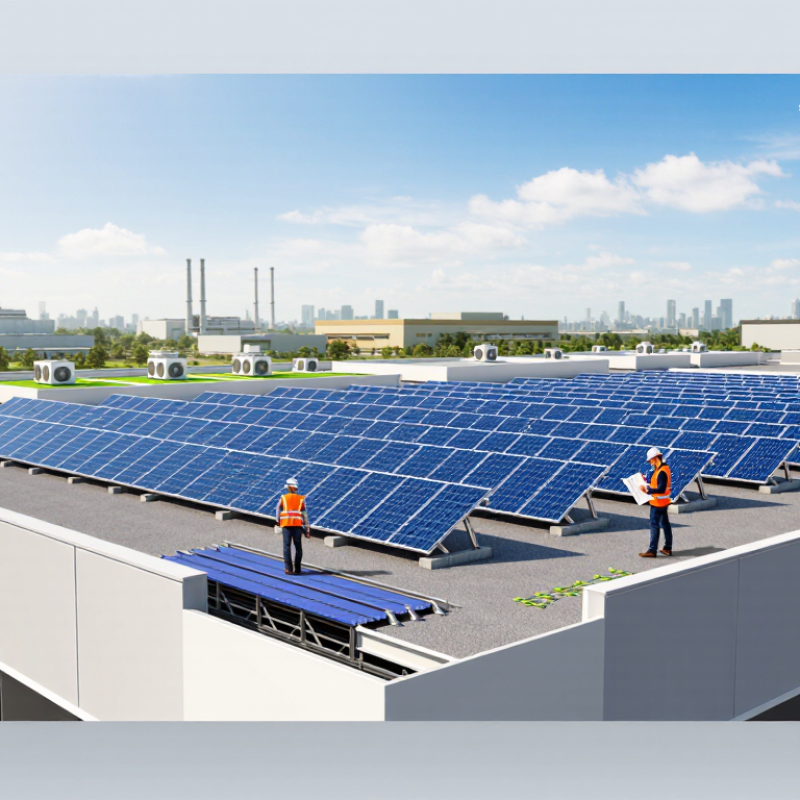
Commercial solar compliance in 2026 depends on the adopted codes, not the project date alone. Local authorities may enforce different editions of the IBC, IFC, NEC, and ASCE 7. The 2024 IBC and ASCE 7-22 commonly guide structural reviews in the United States. Other regions may apply national building standards and separate electrical rules.
The roof must support module weight, racking, ballast, snow drift, wind uplift, and seismic effects. Engineers should verify existing members, connections, parapets, drains, and waterproofing before design approval. A useful field detail is the roof survey: inspectors record corrosion, ponding water, membrane age, and fastener spacing. These small observations can change the entire layout.
The IEA PVPS Trends 2024 report recorded more than 400 GW of global photovoltaic additions in 2023, increasing pressure on permitting systems. Regulatory scope now extends beyond structure. Reviews may include fire access pathways, emergency shutdown, rooftop setbacks, electrical labeling, utility interconnection, and worker safety. NFPA 70 and UL 3741 can influence array design, but acceptance still rests with the authority having jurisdiction.
One weakness remains common: designers sometimes rely on typical roof assumptions. That approach can miss local snow accumulation or aged decking. Early coordination with the structural engineer, fire official, utility, and building department is safer. Forecasts are useful, but site records still decide compliance.
Existing Roof Assessment for Commercial Solar Installation
Commercial solar planning starts with the roof, not the panel layout. IEA PVPS reported 407.3 GW of new photovoltaic capacity worldwide in 2023. That growth increases pressure to reuse existing buildings. Yet older roofs can hide corrosion, weakened joists, trapped moisture, or undocumented alterations. Old roofs surprise us.
A qualified structural engineer should review original drawings, maintenance records, and current site conditions. Field verification must check purlins, beams, columns, fasteners, parapets, drains, and rooftop equipment. The assessment should apply ASCE 7-22 load provisions, including dead, live, wind, snow, and seismic loads. Typical solar modules and racking may add roughly 2 to 4 pounds per square foot. Ballasted systems can impose much higher localized loads. Small details matter.
NREL’s 2024 Solar Industry Update recorded 32.4 GWdc of new U.S. solar capacity in 2023. More retrofit projects now require careful coordination between roofing and structural teams. Roof age alone does not determine suitability. A newer membrane may still lack adequate attachment capacity. A stronger deck may still contain leaks around penetrations. I have seen preliminary layouts pass a desktop review, then fail during field inspection. That is an uncomfortable gap, but it is real. Engineers should map drainage paths, preserve repair zones, and test questionable materials before final design. Some assessments remain imperfect when records are missing. That uncertainty should be documented, priced, and reviewed before procurement.
| Assessment Dimension | Recommended Requirement or Check | Typical Evidence or Calculation | Acceptance Consideration |
|---|---|---|---|
| Roof Documentation | Collect structural drawings, roof plans, previous alteration records, repair history, and available as-built information before design. | Stamped drawings where available, permit records, maintenance logs, and field measurements. | Missing or unreliable records require additional field investigation and conservative assumptions. |
| Roof Age and Remaining Service Life | Confirm membrane, coating, insulation, deck, and flashing condition. Coordinate solar installation with planned roof replacement. | Roof inspection report, moisture survey, warranty information, and expected replacement timeline. | Avoid installing over a roof requiring near-term replacement unless the removal and reinstatement plan is approved. |
| Roof Deck Condition | Inspect metal, concrete, wood, or composite deck for corrosion, deterioration, delamination, water damage, and inadequate fastening. | Exposed-deck observations, fastener pull tests where needed, thickness measurements, and localized probes. | Damaged or weakened deck areas must be repaired before solar supports are installed. |
| Existing Structural System | Identify joists, rafters, trusses, beams, purlins, columns, connections, spans, spacing, and load paths. | Measured framing layout, structural drawings, exploratory openings, and structural calculations. | The support design should transfer gravity, wind, snow, and seismic forces into verified structural members. |
| Solar Dead Load | Include modules, rails, clamps, attachments, ballast, wiring, protective equipment, and any added walkways or maintenance platforms. | Equipment schedule and governing load combinations from the structural design. | Do not use a generic panel-only weight; the total installed system load must be evaluated. |
| Additional Dead Load | Account for existing rooftop equipment, pipes, mechanical units, signs, suspended utilities, and future planned additions. | Field inventory, equipment weights, support reactions, and updated roof loading plan. | Evaluate concentrated loads and load accumulation near beams, columns, curbs, and penetrations. |
| Roof Live Load | Check code-required roof live load and whether maintenance access, construction activity, or designated service areas create additional demand. | Applicable building-code provisions, occupancy classification, roof access plan, and load combinations. | Solar equipment generally does not eliminate the need to consider applicable roof live-load requirements. |
| Snow and Rain Loads | Evaluate ground snow, roof snow, drift, sliding snow, ponding, and rain-on-snow effects where applicable. | Site-specific code maps, roof geometry, parapets, obstructions, drainage layout, and structural load combinations. | Panel arrays must not obstruct drainage or create unaccounted snow-drift and ponding conditions. |
| Wind Uplift and Lateral Forces | Design for roof-zone pressures, edge and corner effects, uplift, sliding, overturning, and load transfer through attachments or ballast. | Site wind speed, exposure, building height, enclosure classification, roof zones, and attachment or ballast calculations. | Edge and corner arrays usually require more stringent restraint than interior arrays. |
| Seismic Effects | Assess seismic attachment, component restraint, equipment anchorage, and interaction with the existing structural system where required by the adopted code. | Site seismic parameters, risk category, component coefficients, anchorage details, and structural calculations. | Use the jurisdiction’s adopted seismic provisions rather than relying on a standard national assumption. |
| Ballasted System Review | Verify ballast weight, friction, roof slope, membrane compatibility, uplift resistance, sliding, overturning, and localized bearing. | Ballast layout, support-pad reactions, wind-tunnel or engineering data where required, and roof loading map. | Ballast can substantially increase dead load and may require reinforcement of the roof structure. |
| Attachment and Fastener Capacity | Check fastener tension, shear, pull-out, edge distance, corrosion resistance, substrate thickness, and connection eccentricity. | Approved engineering data, substrate verification, pull testing where appropriate, and connection calculations. | Fasteners must engage adequate structural material; attachment to a weak roof skin alone may be insufficient. |
| Roof Penetrations and Waterproofing | Map penetrations, curbs, drains, seams, expansion joints, and flashing details before finalizing the array. | Roof plan, penetration schedule, approved details, installation method, and inspection records. | Maintain drainage, movement joints, fire access paths, and watertight flashing at every penetration. |
| Roof Drainage and Ponding | Confirm drains, scuppers, gutters, overflow routes, slopes, and access for cleaning and inspection remain functional. | Drainage survey, roof slope plan, ponding assessment, and array setback dimensions. | Panels, supports, cables, and ballast must not block primary or secondary drainage systems. |
| Deflection and Serviceability | Review member deflection, vibration, ponding sensitivity, module support movement, and connection deformation. | Service-load analysis, roof slope, drainage behavior, framing span, and manufacturer installation limits. | Strength capacity alone is not sufficient if movement could damage modules, wiring, roofing, or attachments. |
| Fire and Emergency Access | Lay out pathways, setbacks, ventilation routes, access points, and firefighter clearances according to the adopted fire and building codes. | Code-compliant roof plan, pathway dimensions, rapid-shutdown design, and authority review. | Requirements vary by jurisdiction, roof type, occupancy, array configuration, and adopted code edition. |
| Electrical and Structural Coordination | Coordinate conduits, inverter equipment, disconnects, cable trays, equipment pads, and attachment points with the structural design. | Coordinated electrical and structural drawings, equipment weights, support reactions, and routing plan. | Avoid unsupported cable runs, trip hazards, membrane damage, and unplanned concentrated equipment loads. |
| Corrosion and Material Compatibility | Evaluate coastal exposure, industrial pollutants, dissimilar metals, protective coatings, drainage water, and contact with roofing materials. | Environmental exposure classification, material schedule, isolation details, and corrosion-control specification. | Use compatible materials and prevent galvanic corrosion at rails, fasteners, flashings, and support interfaces. |
| Construction and Temporary Loads | Plan loading from material staging, workers, carts, lifting equipment, temporary supports, and construction traffic. | Construction logistics plan, temporary load limits, delivery routes, and protection measures. | Temporary construction loads may govern localized areas even when the completed system is structurally acceptable. |
| Structural Analysis and Peer Review | Prepare calculations for existing members, connections, foundations where affected, and all governing load combinations. | Signed and sealed structural drawings, calculation package, site-specific assumptions, and independent review when required. | Use the building official’s adopted codes and locally applicable design criteria; generic templates are not a substitute for site analysis. |
| Final Inspection and Maintenance | Document installation, torque, flashing, roof repairs, drainage clearance, module condition, and post-installation inspection intervals. | As-built drawings, inspection reports, photographs, torque records, maintenance plan, and warranty documentation. | Acceptance should confirm both structural performance and continued roof serviceability. |
Note: Final structural requirements depend on the project location, adopted building and fire codes, roof construction, occupancy, environmental loads, and authority-having-jurisdiction review.
Commercial solar design begins with a continuous load path. Module weight, wind uplift, snow, seismic forces, and maintenance loads must reach the roof structure safely. A qualified structural engineer should trace these forces from the panels through the racking, attachments, deck, joists, and supporting columns.
Dead load is only one concern. Roof framing may also experience drifting snow, ponding water, thermal movement, and uneven equipment loads. Existing drawings can be incomplete. Field verification matters. Inspect the deck condition, corrosion, fastener locations, and any previous repairs before finalizing the layout. Small errors here can become expensive failures.
Racking should match the roof geometry and the calculated load zones. Edge and corner areas often require closer attachment spacing because wind pressures increase there. Attachments must resist tension, shear, and lateral movement without damaging the membrane or deck. Penetrations need compatible flashing and documented installation procedures. Ballasted systems still require checks for sliding, overturning, roof capacity, and drainage paths.
Do not rely on generic spacing tables alone. They may ignore local exposure, parapet effects, or unusual framing. That assumption deserves review. Calculations should reflect the adopted building requirements, site conditions, and the actual equipment arrangement. Keep stamped drawings, product data, inspection records, and attachment test results together. Clear documentation helps reviewers identify weak assumptions before construction begins.
2026 Best Commercial Solar Roof Structural Requirements?
Commercial solar roofs in 2026 must resist more than panel weight. Engineers should verify the complete load path, from modules and rails to beams, columns, and foundations. Wind uplift often controls edge and corner zones, where suction is strongest. Fasteners, clamps, and roof attachments need tested capacities and corrosion-resistant details.
Snow design requires both uniform weight and drifting near parapets, equipment, and height changes. Heavy wet snow can exceed a simple panel-load estimate. Seismic review should consider rack movement, equipment anchorage, flexible connections, and falling hazards. A stiff array may transfer unexpected forces into an older roof. That detail is easy to miss.
Fire performance depends on the roof assembly, module layout, access paths, and local fire requirements. Keep clear routes for emergency operations. Water resistance also deserves close attention. Every penetration needs compatible flashing, proper sealant, and a drainage plan that avoids ponding. Ballasted systems reduce penetrations, but they add weight and may shift under wind or seismic movement. Field inspections should check cracked membranes, loose hardware, blocked drains, and damaged insulation. A drawing can look complete while the roof tells another story. No checklist is perfect. Reconfirm assumptions with a licensed structural professional and the authority having jurisdiction before construction.
Commercial solar roof projects in 2026 require more than panel layouts and production estimates. A licensed structural engineer should review the roof’s age, framing, connections, and existing loads. The design must account for panel weight, ballast, wind uplift, snow, seismic forces, and maintenance access. Local conditions matter greatly.
Engineering documents should include stamped calculations, structural drawings, attachment details, equipment weights, and roof condition records. These documents help reviewers understand how loads move into beams, joists, and foundations. A clear roof plan should show fire access paths, setbacks, drainage points, and equipment locations. Small omissions can delay approval.
Permits usually involve building, electrical, and sometimes fire authorities. Requirements vary by jurisdiction and by the codes adopted there. Do not rely on an old permit package. Inspections may check flashing, fasteners, grounding, wiring, and structural connections before concealment. Photographs help, but they cannot replace an inspection.
Maintenance begins after commissioning. Schedule roof walks, drainage checks, corrosion reviews, cable inspections, and thermal imaging when appropriate. Keep records of repairs, leaks, inverter alerts, and inspection dates. A blocked drain can create a serious problem. So can a loose attachment.
One practical weakness deserves attention: many owners plan installation but underfund future roof repairs. Solar equipment may need temporary removal during reroofing. That cost should be discussed before construction. A reliable project leaves the owner with updated drawings, permit records, inspection results, warranties, and a realistic maintenance schedule.
Compliance depends on locally adopted building, fire, electrical, and structural codes. Different regions may enforce different editions. The project date alone does not decide requirements.
Inspectors should record corrosion, ponding water, membrane age, deck damage, and fastener spacing. They should also review parapets, drains, connections, and previous repairs. Site records matter.
The roof must support module weight, racking, ballast, snow, wind uplift, seismic forces, and maintenance loads. Snow drifting near parapets may create heavier local loads. Simple weight estimates can mislead.
Engineers should trace forces from modules through rails, attachments, decking, joists, columns, and foundations. Every connection needs adequate tension, shear, and lateral resistance. The path must stay continuous.
Usually not. Generic tables may overlook local wind exposure, roof edges, parapets, snow, or unusual framing. Calculations should match the actual equipment arrangement and site conditions.
Ballasted systems still require checks for sliding, overturning, roof capacity, drainage, wind, and seismic movement. They reduce penetrations but increase roof weight. That tradeoff deserves review.
Reviews may include clear fire pathways, rooftop setbacks, emergency shutdown, labeling, and safe worker access. Array layouts should leave practical routes for emergency operations. Drawings must reflect local acceptance.
No. Reviewers may also need product data, inspection records, attachment tests, field surveys, and utility documents. A drawing can look complete while the roof shows hidden deterioration. Some assumptions may still be wrong.
In 2026, commercial solar roof projects must address building codes, electrical regulations, fire-safety rules, and local permitting requirements from the earliest planning stage. A complete roof assessment should verify the roof’s age, condition, drainage, waterproofing, and remaining service life before installation. Engineers must evaluate the full structural load path, including panels, racking, attachments, ballast, and connections to the building frame. The key question is: What are the structural requirements for a commercial solar roof? The answer depends on the building design, roof system, climate, and project location.
Design documents should account for wind uplift, snow accumulation, seismic movement, fire access, water resistance, and safe maintenance routes. Professional calculations, drawings, equipment specifications, and permit applications may be required before construction begins. Inspections should confirm that attachments, flashings, wiring pathways, and protective systems are installed correctly. After completion, regular inspections and maintenance can help identify corrosion, leaks, damaged modules, loose connections, and changes in roof performance, supporting long-term safety and reliability.

Illumino Solar